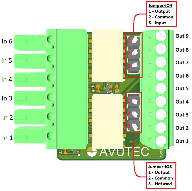
Figure 1: IO extender schematic
The IO Extender V2 can be connected via the input connector (left connector in Figure 1) to the
Gatekeeper. The multiple output functions are presented to the user via the output connector
(right connector in Figure 1).
Output connector: electrical characteristics of the output connector
Signal |
Parameters |
Min. |
Typ. |
Max. |
Unit |
|---|---|---|---|---|---|
Data signal D0/D1 |
High-level |
4.8 |
5.0 |
5.5 |
V |
Low-level |
0 |
V |
|||
Frequency |
1 |
MHz |
|||
Relay A,B |
Switching current |
1000 |
mA |
||
Switching voltage AC |
58 |
V |
|||
Switching voltage DC |
50 |
V |
|||
Input mode pin Out 8 |
Sink current |
30 |
mA |
||
High-level |
5.5 |
12 |
V |
||
Low-level |
0 |
V |