The IO extender is a level shifter and relay-board in one, that can be used as an extender of the IO pins in the back of all Gatekeeper and Gatekeeper-X models.
It is used to generate a Wiegand signal and communicate with external electronic devices.
Junctionbox at the back of the Gatekeeper-X
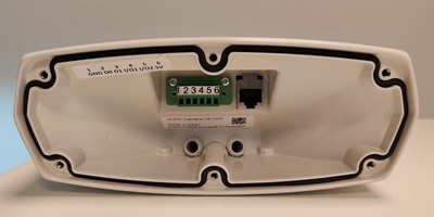
Pin Number |
Signal Name |
|---|---|
1 |
Ground |
2 |
Data0 |
3 |
Data1 |
4 |
IO1 |
5 |
IO2 |
6 |
3.3V |
Wiegand
In access control solutions a Wiegand signal is often required. The IO pins as they come in the back of the Gatekeeper have an output voltage of 3.3V.
The IO extender shifts the Wiegand signal generated by CortexFramework to 5V.
To send a Wiegand signal connect wires to D0, D1 and GND.
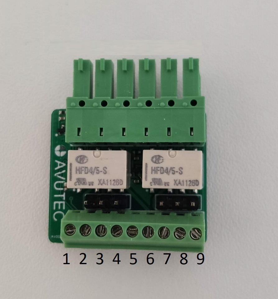
Pin number |
Signal |
Description |
|---|---|---|
1 |
GND |
|
2 |
D1 |
|
3 |
D0 |
(Autonomous) opening a barrier
To open a barrier (without a third party access controller) the IO extender has two electronic relays to switch a voltage high enough to open a gate.
Relay A (pin 4,5,6) and Relay B (pin 7,8,9) can be used to operate two individual barriers.
Set jumpers to output mode (see "Pin description" tabel 3)
When using the relay functionality of the I/O extender, a Metal Oxide Varistaror (MOV) over the contacts of the screw terminals of the extender should be used to protect the Gatekeeper from switching and induced surges.
Relay type: Axicom IM03GR
The maximum switching voltage: 48VDC
Rated current is: 1A.
Pin number |
Signal |
Description |
4 |
Relay B NC |
|
5 |
Relay B COM |
Switch IO3 jumper to output mode |
6 |
Relay B NO |
|
7 |
Relay A NC |
|
8 |
Relay A COM |
Switch IO4 jumper to output mode |
9 |
Relay A NO |
Receiving input from third party devices
The IO extender can be used to receive DC input signals.
•Set jumper IO4 in input mode by connecting pin 2 and 3. Jumper IO3 should always be set to output mode.
•Pin Out 8 can receive max 12 VDC. >=5.5VDC=high, <5.5 VDC=low
•In CortexClient, the GatekeeperAxon, set relay to input mode.
Set jumpers to input mode (see "Pin description" tabel 4)
Relay type: Axicom IM03GR
The maximum switching voltage: 48VDC
Rated current is: 1A.
Pin number |
Signal |
Description |
8 |
VDC Input |
Switch IO4 jumper for input mode |